Constructing a Syntax Graph
In the previous paragraph, a top-down recognition algorithm was presented that is applicable to grammars satisfying the restrictive Rules 1 and 2. We now turn to the problem of converting this algorithm into a concrete program. There are two essentially different techniques that can be applied. One is to design a general top-down parsing program valid for all possible grammars (satisfying Rules 1 and 2). In this case, particular grammars are to be supplied in the form of some data structure, on the basis of which the program operates. This general parser is in some sense controlled by the data structure; the program is then called table driven. The other technique is to develop a top-down parsing program which is specific for the given language and to construct it systematically according to a set of rules which map a given syntax into a sequence of statements, i.e., into a program. Both techniques have their advantages and disadvantages; both will be introduced subsequently. In the development of a compiler for a given programming language the high degree of flexibility and parametrization of the general parser are hardly needed, whereas the specific parser approach usually leads to more efficient and more easily manageable systems and is therefore preferable. In both cases it is advantageous to represent the given syntax by a so-called recognition- or syntaxgraph. This graph reflects the flow of control during the process of parsing a sentence.
It is a characteristic of the top-down approach that the goal of the parsing process is known at the start. The goal is to recognize a sentence, i.e., a sequence of symbols generatable from the start symbol. The application of a production, that is, the replacement of a single symbol by a sequence of symbols, corresponds to the splitting up of a single goal into a number of subgoals to be pursued in specified order. The top-down method is therefore also called goal-oriented parsing. In constructing a parser it is easy to take advantage of this obvious correspondence of non-terminal symbols and goals: we construct a subparser for each non-terminal symbol. Each subparser has the goal of recognizing a subsentence generatable from its corresponding non-terminal symbol. Since we wish to construct a graph to represent the total parser, each non-terminal will be mapped into a subgraph. This leads us to the following rules for constructing a recognizer graph.

is mapped into a recognition graph A, whose structure is determined by the righthand side of the production according to Rules A2 through

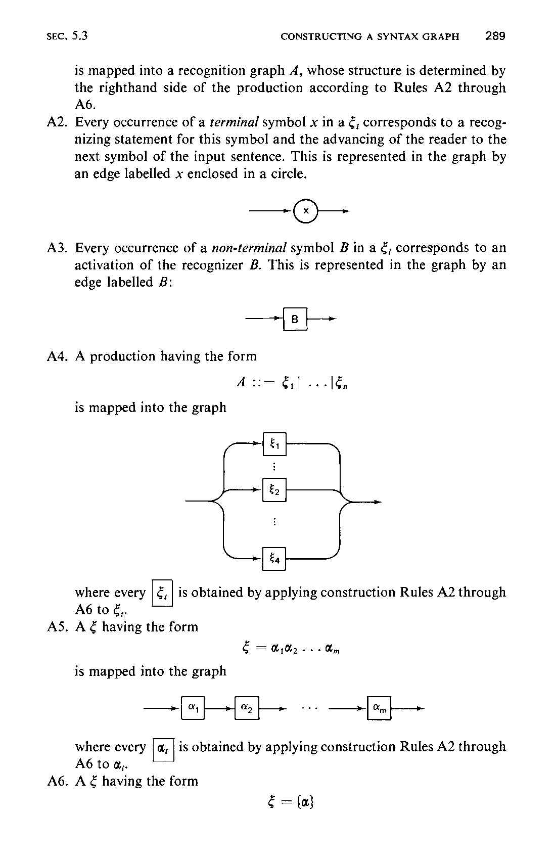
A2. Every occurrence of a terminal symbol x in a €; corresponds to a recog-
nizing statement for this symbol and the advancing of the reader to the next symbol of the input sentence. This is represented in the graph by an edge labelled x enclosed in a circle.
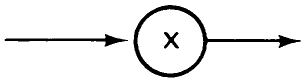
A3. Every occurrence of a non-terminal symbol B in a €; corresponds to an
activation of the recognizer B. This is represented in the graph by an edge labelled B:
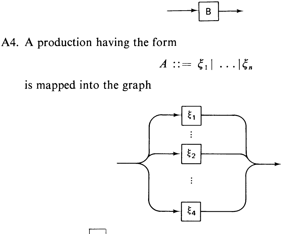
where every is obtained by applying construction Rules A2 through
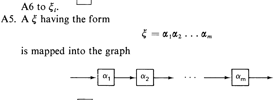
where every is obtained by applying construction Rules A2 through
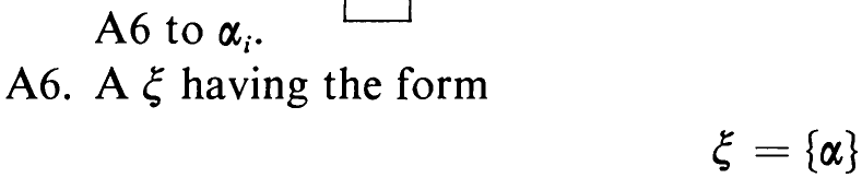
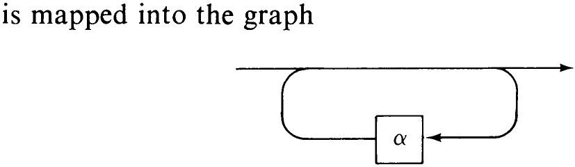
where [a | is obtained by applying construction Rules A2 through A6 to a.

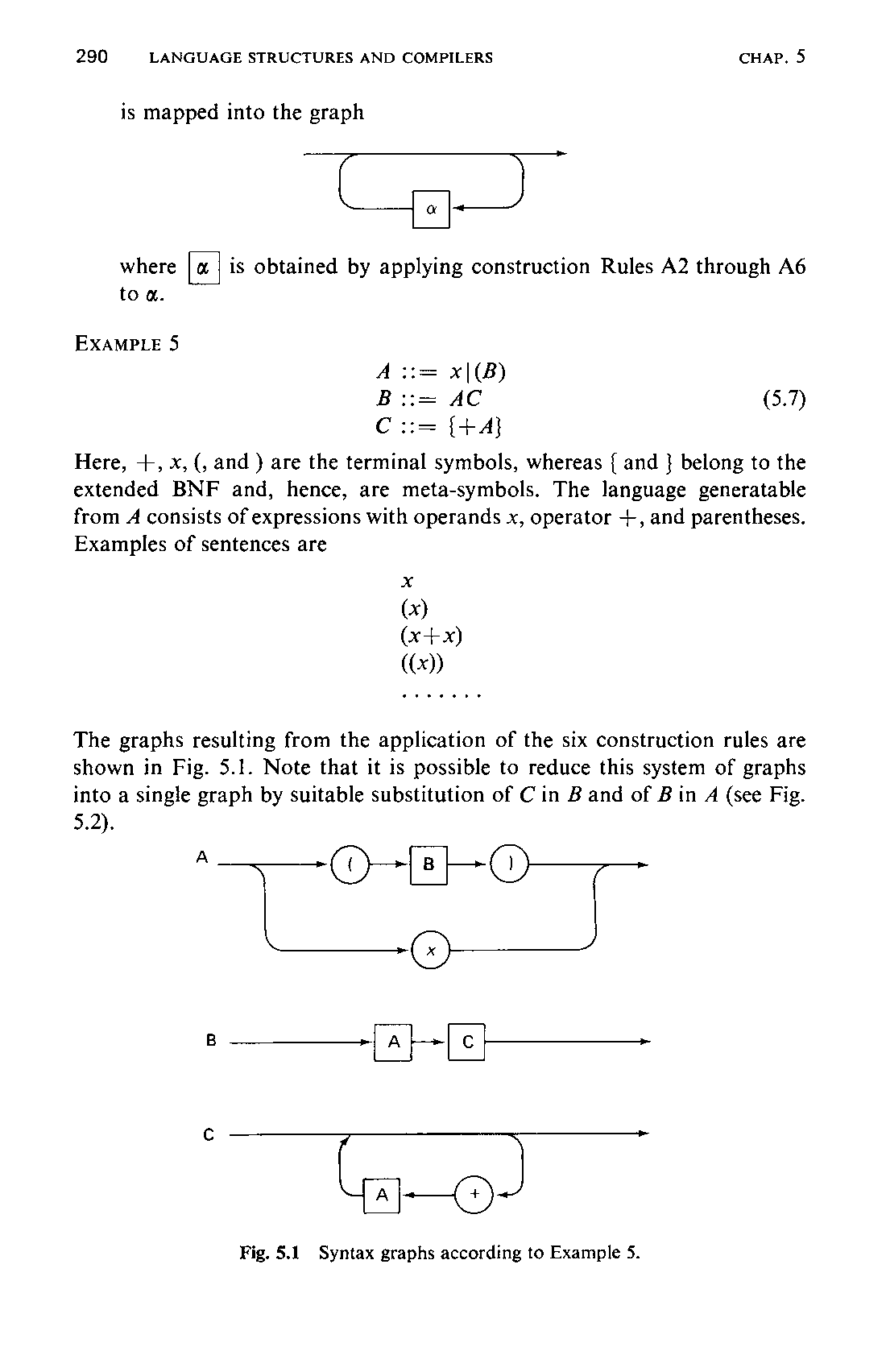
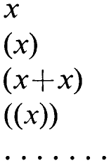
Here, +, x, (, and ) are the terminal symbols, whereas { and } belong to the extended BNF and, hence, are meta-symbols. The language generatable from A consists of expressions with operands x, operator +, and parentheses. Examples of sentences are
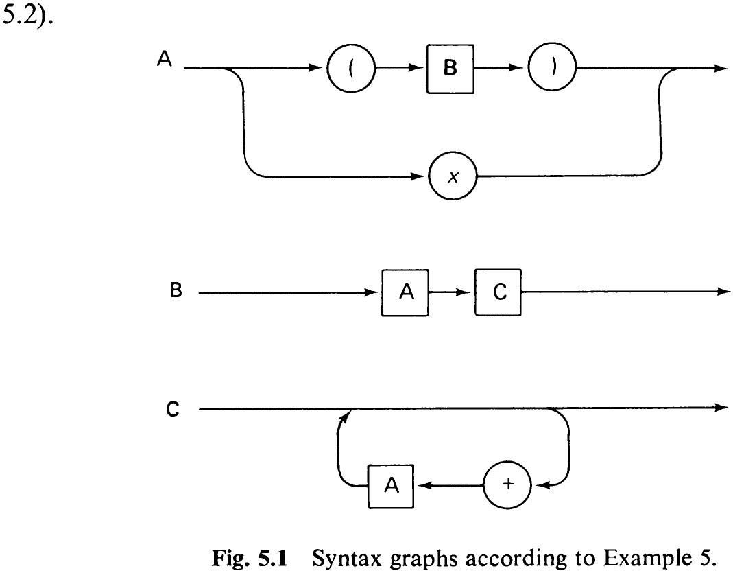
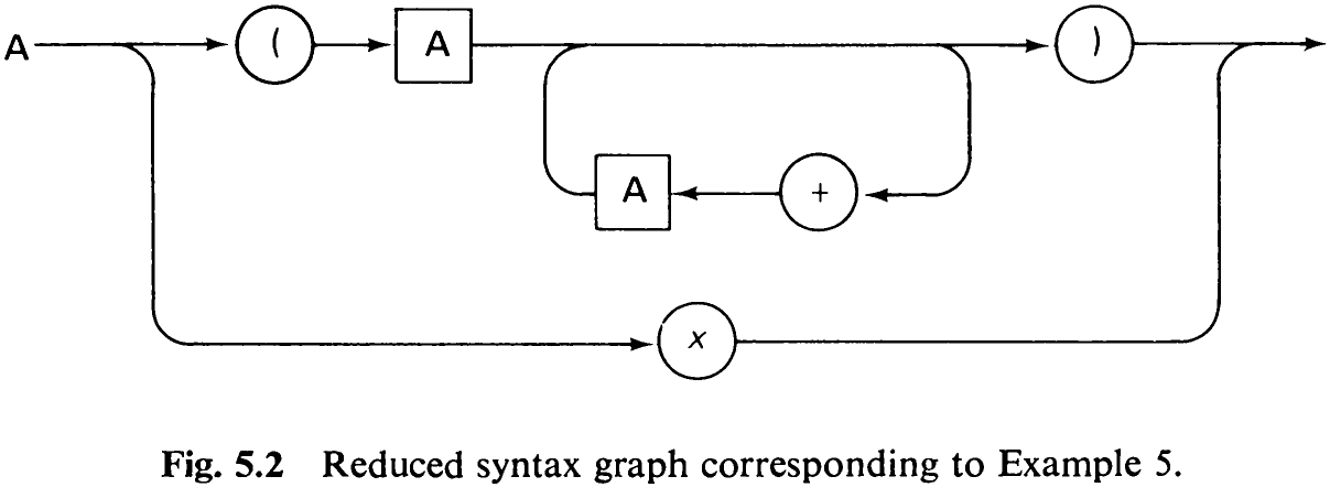
The graphs resulting from the application of the six construction rules are shown in Fig. 5.1. Note that it is possible to reduce this system of graphs into a single graph by suitable substitution of C in B and of B in A (see Fig.
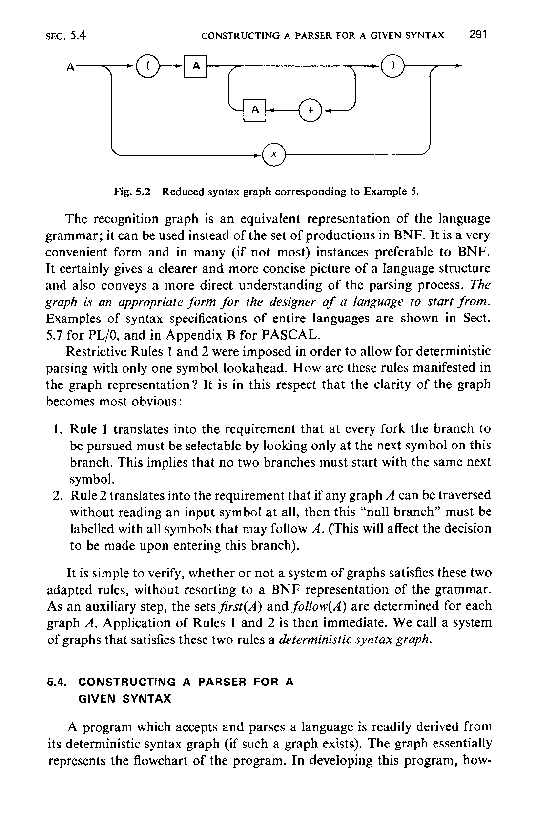
The recognition graph is an equivalent representation of the language grammar; it can be used instead of the set of productions in BNF. It is a very convenient form and in many (if not most) instances preferable to BNF. It certainly gives a clearer and more concise picture of a language structure and also conveys a more direct understanding of the parsing process. The graph is an appropriate form for the designer of a language to start from. Examples of syntax specifications of entire languages are shown in Sect. 5.7 for PL/O, and in Appendix B for PASCAL.
Restrictive Rules 1 and 2 were imposed in order to allow for deterministic parsing with only one symbol lookahead. How are these rules manifested in the graph representation? It is in this respect that the clarity of the graph becomes most obvious:
-
Rule 1 translates into the requirement that at every fork the branch to be pursued must be selectable by looking only at the next symbol on this branch. This implies that no two branches must start with the same next symbol.
-
Rule 2 translates into the requirement that if any graph A can be traversed without reading an input symbol at all, then this “null branch” must be labelled with all symbols that may follow A. (This will affect the decision to be made upon entering this branch).
It is simple to verify, whether or not a system of graphs satisfies these two adapted rules, without resorting to a BNF representation of the grammar. As an auxiliary step, the sets first(A) and follow(A) are determined for each graph A. Application of Rules 1 and 2 is then immediate. We call a system of graphs that satisfies these two rules a deterministic syntax graph.